THE OIL GRID is a patented, decentralised, modular oil and gas production system. In place of the century-old central plant, it is designed to put a sealed, self-energised unit at each well, join the units with a buried ring, and run the field with artificial intelligence.
One idea, turned around
For a century, raw fluid has travelled to the factory. THE OIL GRID reverses the direction. Instead of moving the raw materials to the factory, it moves the factory to the raw materials.
Four kinds of infrastructure leave the design: the central gathering centre, the tank farm, the flare stack and the central power plant. Five words describe what remains: decentralised, modular, self-energised, AI-controlled, subterranean.
What a field looks like
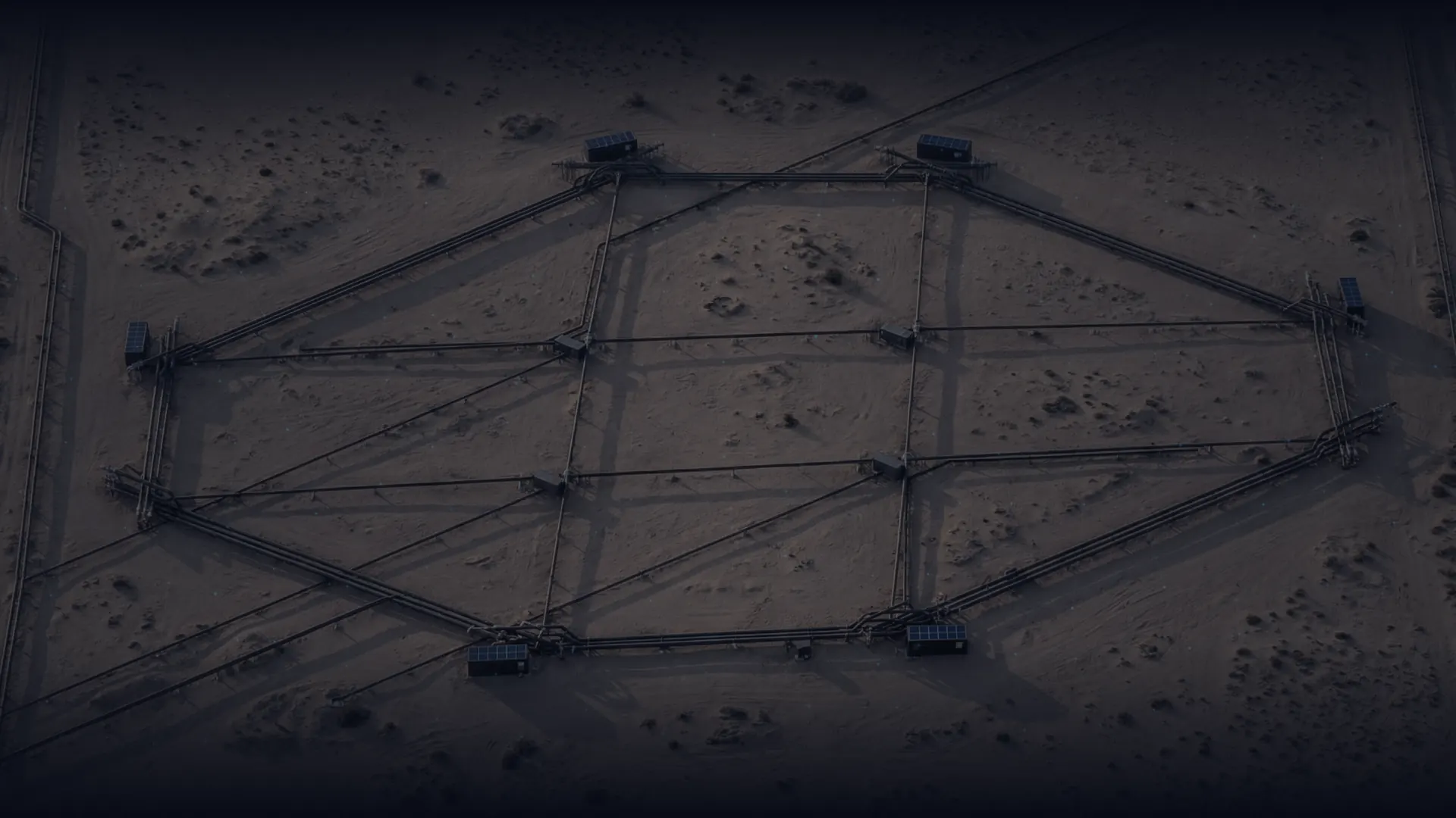
Picture a field laid out on THE OIL GRID. The first thing a visitor would notice is what is missing: no central plant on the horizon, no tank farm, and no flare stack on the skyline.
At each well, the design places a sealed unit about the size of a load truck. The pipelines would be out of sight, buried in a ring beneath the ground. A control station would watch over the whole field, and at the ring's low point a compact dispatch station would hand finished oil and gas to the customer. Much of the land would be left free for other use.
Four subsystems, one architecture
Three subsystems handle the product: they gather it, move it and dispatch it. The fourth, the AI-CS, directs all of them, and it answers to the Smart Field, the governing intelligence of the whole project.
01 · SERM-GC · Self Energised Remote Mini Gathering Centre
A complete gathering centre in miniature, placed at the wellhead: usually one unit per well, sized to that well. The sealed unit is designed to separate the stream into oil, gas and water and send each on its own line, and to manage pressure inside itself; it carries its own fire and explosion protection. It is designed to power itself from energy already at the well site. Factory-built and about the size of a load truck, it is designed to move to another well when its work in one place is done.
02 · CL Unit · the Circle Pipeline, the Oil-Grid
A closed ring, buried beneath the field, that joins every SERM-GC: three lines in one trench, for oil, gas and water. Product can travel either way around the ring, so an offline segment is designed to be bypassed rather than shut the field down. The pipeline is also the field's reservoir, so no surface tank is needed, and a new well joins the ring as it comes on stream.
03 · AI-CS · AI Control Station, under the Smart Field
The field's central intelligence. Every unit carries its own local AI, which reports to the AI-CS and acts on its instructions. The AI-CS is designed to monitor, predict and optimise the field around the clock, and to alert the owner when a unit needs attention. The aim is to keep people out of hazardous areas. Above the AI-CS, the Smart Field sets the production plan for the whole project from operator input, customer requirements and live field data. If communication is lost, each unit is designed to hold itself in a safe state.
04 · DS · Product Dispatch Station
Where the finished product leaves the grid. At the ring's low point, the DS is designed to remove remaining impurities, bring the crude to the customer's specification and heat it where needed, and to send oil and gas on to refineries, trunklines and customers, and water to re-injection or treatment. Metering and custody transfer are built in, so ownership changes hands only after the product has been cleaned, upgraded and metered. The DS holds no storage tanks.
In the design, the stream is separated as it leaves the well. Oil, gas and water then travel the ring on their own lines to the DS, and on to the customer or to re-injection, under the Smart Field's plan.
The system is designed to take a field from zero to full capacity with one command, and to start up and shut down in minutes rather than days. Production is designed to begin with the first commissioned units, and to grow as each new well joins the ring.
When something goes wrong, the design keeps the problem small. A fault is designed to stop one well while the rest of the field keeps producing. The AI is designed to alert the owner in real time, and the unit is planned to be exchanged for a working one within about two days. Local damage is designed to be isolated and repaired without shutting down the field.
What is new, and what is not
THE OIL GRID is built from equipment the industry already knows and trusts: separators, valves, pipelines, pumps, sensors, meters and control systems. What is new is the way that equipment is put together. Each subsystem is a new combination of established equipment, and the four are joined under the Smart Field into one production architecture.
THE OIL GRID is patented in the United States (US Patent 9,334,722 B1, granted in 2016), and the design has been refined continuously since.
What it is designed to deliver
The benefits are designed to follow from the architecture. What the design removes no longer has to be built, powered, manned or protected.
The percentages and the cycle figure below are results of process simulation against a defined reference case — a virgin (greenfield) onshore field with no existing supporting utilities — and are not real or measured figures. Actual results can vary widely from field to field, and may be much lower. Where such infrastructure already exists, the advantage narrows. The rest are properties or intents of the design.
Simulated range · Varies by fieldfaster deploymentMost Oil Grid projects are planned to take 5–7 years from decision to full build-out, against 18–21 years for a conventional, centrally-gathered field — around 60–75% faster depending on field conditions. Units are designed to start producing as they are installed, instead of every well waiting for one plant to be finished.Source: Global Energy Monitor — recent major field developments average 15–16 years; complex ones 18–23 years.
↑60–75%60–75%
faster deployment
Process-simulation result · Greenfield reference case · Not a real or measured figure
Simulation · Varies by fieldlower CAPEXNo central plant, no tank farm, no flare system, and no power plant or substation — the units are self-energised. Standardised, factory-built units replace a bespoke plant. About 40% at the floor, where a site already has utilities; around 49% on average across fields; and up to 70% on the reference case, a virgin field with none.
↓Up to70%70%
lower CAPEX
Process-simulation result · Greenfield reference case · Not a real or measured figure
Simulation · Varies by fieldlower OPEXEach unit is designed to run on energy already at the wellsite, to need no permanent crew stationed beside it, and to be maintained by swapping the unit rather than shutting down a plant — cutting maintenance, operation and labour costs together.
↓Up to70%70%
lower OPEX
Process-simulation result · Greenfield reference case · Not a real or measured figure
Simulation · Varies by fieldenergy consumptionEvery SERM-GC is designed to power itself from gas pressure, solar or the well's own heat instead of drawing external power, and there is no central plant, compressor train or tank farm to run. Conventional and non-conventional generation on site covers the rest.
↓Up to80%80%
energy consumption
Process-simulation result · Greenfield reference case · Not a real or measured figure
Simulation · Varies by fieldsmaller footprintThe field is estimated to use roughly 40% of the land a conventional layout needs. Because it is designed to be AI-driven and run remotely, almost no one is planned to be on site — no offices, accommodation, workshops, warehouses or storage — and there is no central plant, tank farm, flare zone, surface corridor, power plant or substation. Truck-sized units at the wells; the ring underground.
↓Up to60%60%
smaller footprint
Process-simulation result · Greenfield reference case · Not a real or measured figure
Simulation · Varies by fieldproduction lost to downtimeIndustry data: conventional fields lose about 8% of their potential production to unplanned downtime — roughly a month of output a year — because one gathering-centre fault stops every well behind it. In THE OIL GRID a fault is designed to stop one well only — usually one unit serves one well: the AI is designed to alert the owner in real time and ask for immediate attention, and the unit is planned to be swapped for a working one within about two days while the ring is designed to keep flowing.Source: SPE / JPT — unplanned downtime across 190 Gulf of Mexico producing assets.
↓Up to90%90%
production lost to downtime
Process-simulation result · Greenfield reference case · Not a real or measured figure
Simulation · Varies by fielddesign-to-implementation cycle — typically 1–2 yearsBecause the units are standardised and factory-built, engineering, permitting and construction are planned to run in parallel rather than one after the other — and the first units are designed to produce while the rest are still being installed.
1/31/3
design-to-implementation cycle — typically 1–2 years
Process-simulation result · Greenfield reference case · Not a real or measured figure
Design objective · Subject to validationHSE compliantDesigned to full HSE compliance from the start: no flare, no tanks, no open storage — sealed units with fire and explosion protection built in, reduced exposure to sour gas, corrosion, erosion and hydrate formation, and far fewer people stationed in hazardous areas. A design intent: conformity is certified at validation.
100%100%
HSE compliant
Design feature · Not yet builtintelligent AI controlThe local AI in every unit reports to AI-CS, which is designed to monitor, predict and optimise around the clock under Smart Field's overall production plan — and to raise the alarm to the owner when anything needs attention. Production is designed to be taken from zero to full capacity with one command.
24/724/7
intelligent AI control
Design feature · Not yet builthigh, medium or low pressure, any crude typeHigh-, medium- and low-pressure wells and any crude type are designed to be produced in the same project. Each SERM-GC is designed to receive and process the stream regardless of well pressure, within the operating envelope defined for each field, so a field need not be split into what the plant can and can't handle — and marginal wells can become worth producing.
Any wellAny well
high, medium or low pressure, any crude type
Design objective · Subject to validationagainst theft or destruction, by designSealed, contained units; an underground ring with no exposed tank farm or surface corridor; and continuous AI monitoring designed to detect and report any interference in real time. The control systems are designed to the IEC 62443 cybersecurity standard, a design intent confirmed at validation.
SecuredSecured
against theft or destruction, by design
Design feature · Not yet builtsurface tanksHaving no surface tanks removes the fire, spill and evaporation exposure of stored product — nothing sits still long enough to need storing; the integrity of the buried ring is managed as a pipeline. The underground ring itself acts as the buffer, so product is designed to stay in motion towards the Product Dispatch Station.
00
surface tanks
All percentages are "up to" values — upper-bound results of process simulation and engineering calculation from assumed inputs and operational experience — not real or measured figures. No Oil Grid installation has yet been built. They are illustrative and have not been independently audited or validated through a completed project. They are calculated on a virgin (greenfield) field with no existing supporting utilities — no electrical substation, access roads, or gas and water supply; the advantage narrows where such infrastructure already exists, and actual results vary by site. THE OIL GRID is engineered and patented; next comes the one-time design stage — full engineering and manufacturing design, prototype testing, certification and licensing — then the first standard units are manufactured, ready for the first customer.
Some benefits are properties of the design itself: no surface tanks and no flare system [design characteristic]; any well, from high to low pressure, within the operating envelope defined for each field [design characteristic]; intelligent control 24 hours a day [design characteristic]; and physical security by design, with sealed units, a buried ring and no exposed tank farm [design characteristic].
Others are what the system is engineered to meet, to be confirmed at validation: zero routine flaring, which depends on the captured gas having an outlet, with emergency provisions kept under safety standards [design intent]; full HSE compliance [design intent]; and cybersecurity of the control systems to IEC 62443 [design intent].
The full register answers the shortfalls group by group: engineering; health, safety and environment; economic; business; management; logistics; and protection. Each of the thirty-three benefits below carries its claim class.
1 · Engineering
01 · Separation at source
The SERM-GC is designed to separate oil, gas and water at the wellhead and send each on its own line.design characteristic
02 · Wide well and crude compatibility
High-, medium- and low-pressure wells, high gas-oil ratio and different crude types, within the operating envelope defined for each field.design characteristic
03 · Self-energised units
Units are designed to draw on well-stream pressure and heat and permitted local sources, with no central power plant; the energy balance is to be confirmed by prototype testing and certification.design characteristic
04 · Corrosion, erosion and hydrate control built in
Pressure and chemistry are designed to be managed inside the sealed unit, and separation at source shortens raw-fluid transport.design intent
05 · The pipeline as the buffer
The underground ring is designed to provide transport and dynamic buffering, so no surface storage tank is needed.design characteristic
06 · Standardised and factory-built
Repeatable manufacture in place of a bespoke plant built on site.design characteristic
07 · Intelligence in every unit
Each SERM-GC, the CL Unit and the DS carry local AI that reports to the AI-CS under the Smart Field.design characteristic
2 · Health, safety and environment
08 · Zero routine flaring
Gas is designed to be captured and processed at the well; no flare system is fitted; emergency provisions remain under safety standards.design intent
09 · Zero surface tanks
The architecture contains no surface storage tanks; the ring is the buffer.design characteristic
10 · Up to 80% less energy ⓘ
Self-energised units and no central energy-intensive facilities.process simulation
11 · Up to 60% smaller footprint ⓘ
Distributed units and a buried ring; no permanent on-site estate.process simulation
12 · People kept out of hazardous areas
Remote and automated operation is designed to reduce routine presence near hazardous inventory.design intent
13 · Fire and explosion protection in every unit
Protection, detection and shutdown built into each sealed unit.design characteristic
14 · Water handled responsibly
Produced water is designed to be separated at the well and routed to re-injection or treatment.design characteristic
3 · Economic
15 · Up to 70% lower CAPEX ⓘ
About 40% floor, around 49% average, up to 70% on the reference case.process simulation
16 · Up to 70% lower OPEX ⓘ
Automation, energy at the well, no permanent crew, maintenance by unit exchange.process simulation
17 · 60–75% faster deployment ⓘ
5–7 years against 18–21 years for a conventional, centrally gathered field.process simulation
18 · Production before project completion
Units are designed to produce as they are commissioned rather than when the whole field is finished.design characteristic
19 · Up to 90% less production lost to downtime ⓘ
A fault is designed to stop one well only; the unit is planned to be exchanged within about two days.process simulation
20 · Marginal wells become potentially economic
A lower shared-infrastructure burden lowers the cost floor for small and low-pressure wells.commercial or strategic statement
21 · Phased, self-funding growth
Deployment and production can grow as units are commissioned and revenue flows.commercial or strategic statement
4 · Business
22 · A route for new producing nations
A lower infrastructure threshold could make development feasible for resource holders that cannot justify a conventional mega-project.commercial or strategic statement
23 · Multiple partnership routes
Joint venture first; direct procurement, build-operate-transfer and licensing.commercial or strategic statement
24 · Design once, deploy repeatedly
Standardised platform engineering reduces repeated bespoke engineering.commercial or strategic statement
25 · Local manufacturing and the seven-year training programme
Local manufacture with skilled local labour, and a seven-year programme planned to hand operation to the client.commercial or strategic statement
5 · Management
26 · 24/7 intelligent control
The AI-CS and the Smart Field are designed to monitor, coordinate and optimise the field around the clock.design characteristic
27 · Predictive maintenance and alerts
Unit issues are designed to be identified early and reported to the owner in real time.design intent
28 · Design-to-implementation cycle under a third ⓘ
Typically 1–2 years, with engineering, permitting and construction in parallel.process simulation
29 · Per-well metering and customer connectivity
Metering at every well, custody transfer at the DS and connection of customer systems; accuracy is to be confirmed by prototype testing and certification.design characteristic
6 · Logistics
30 · Road-deliverable logistics
Load-truck-sized units and pipe are planned to arrive by road, with no oversized central-plant modules.design characteristic
31 · Relocatable, expandable, resellable
Units can move between wells and projects as a field expands or contracts.design intent
7 · Protection
32 · Security by design
Physical: sealed units, a buried ring and no exposed tank farm (a design characteristic). Cyber: OT/ICS security to IEC 62443 (a design intent).
33 · Strategic resilience and operational continuity
A local failure is designed to be isolated while the rest of the field keeps producing; to be confirmed site by site.design intent
An honest account of risk
THE OIL GRID is designed to remove some conventional risks and reduce others, and it introduces a few new ones.
Designed out: the central gathering centre; the surface tank farm, with the buried ring's integrity managed as a pipeline; and the central power plant, with the energy balance to be confirmed by prototype testing and certification. Routine flaring is designed out as a design intent, with emergency provisions kept under safety standards.
Reduced, not removed: long raw-fluid transport, single-point outages, methane from leaks and venting, bespoke engineering and the heavy construction campaign. Site-specific engineering, leak detection and repair, water treatment and disposal, and decommissioning obligations remain; the buried ring stays a fixed asset.
New, and addressed in the design: cyber exposure, addressed by a control-system security architecture to IEC 62443; distributed maintenance, addressed by unit exchange and predictive maintenance; and dependence on communications, addressed by a safe state that each unit is engineered to hold if the link is lost.
The next step
THE OIL GRID is engineered and patented. No installation has yet been built; next comes the one-time design stage — full engineering and manufacturing design, prototype testing, certification and licensing — then the first standard units are manufactured, ready for the first customer.
Start a Confidential Conversation
The Stakeholder Portal
This page tells the story. If you want the numbers and documents behind it, your portal tier gives you exactly that — from a one-page fact sheet to detailed briefing documents, matched to who you are.